


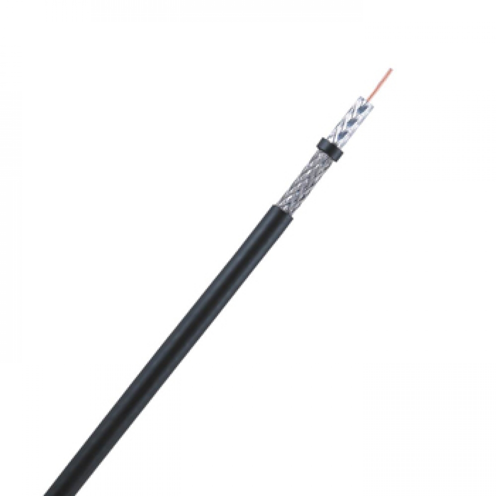
Coaxial Cable
LS Cable & System coaxial cables are tested extensively in every known simulated environmental and electrical performance condition. This guarantees reliable and trouble-free when put to use.
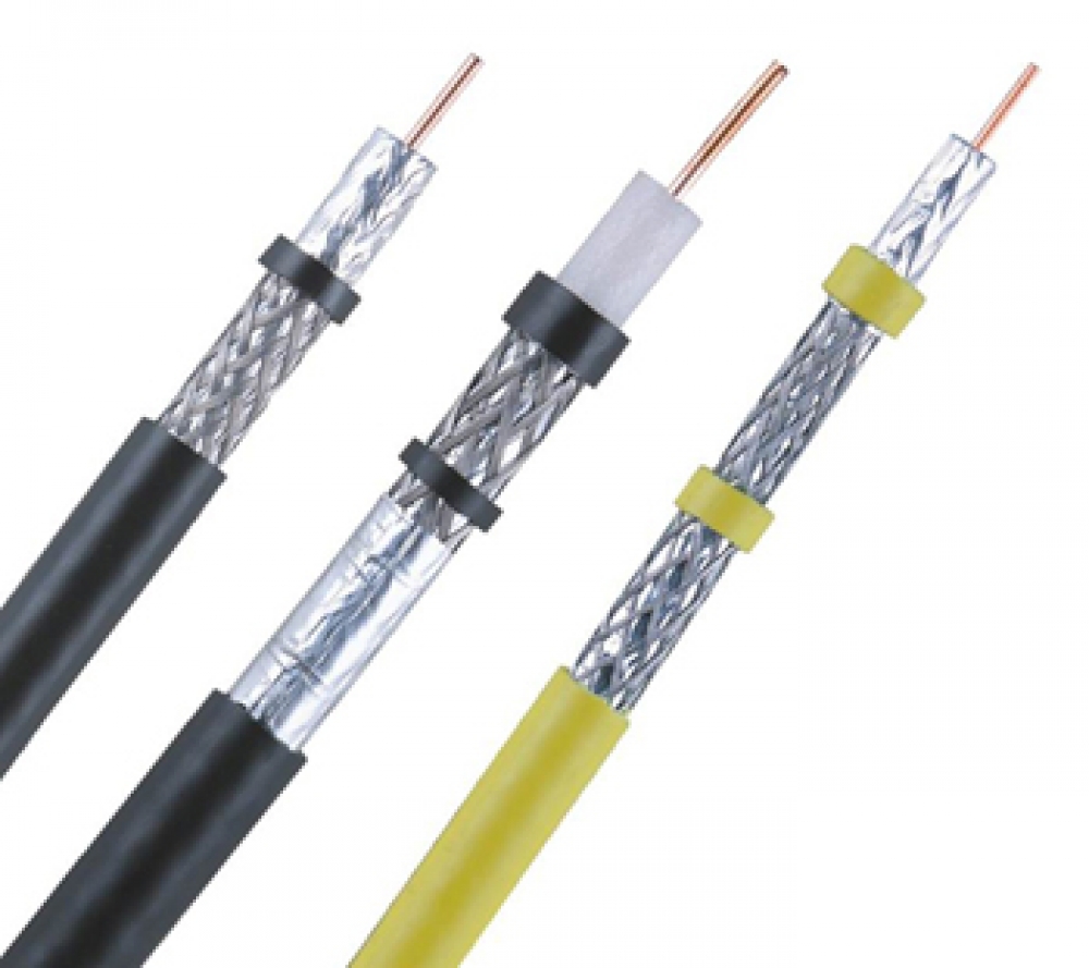
LS Cable & System coaxial cables are engineered and manufactured in a variety of sizes and materials, each offering unique benefits needed for physical, electrical and other various applications.
Coaxial cable choices include broadband, standard analog, precision video for analog and digital, bundled RGB, high-flex SVHS, video triax, conformable coax and more. Coaxial cables feature enhance shielding in a variety of forms to satisify all unique conditions.
Coaxial Cable
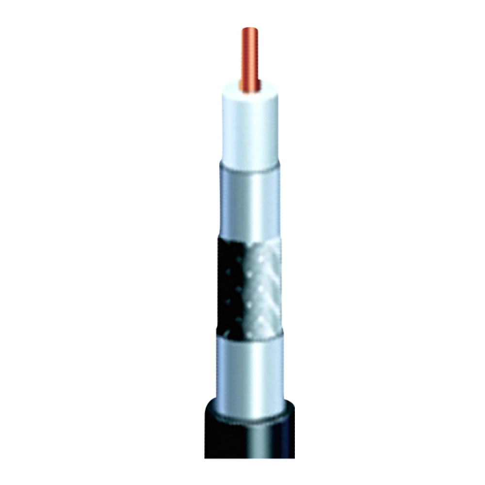
HFBT
- Description
- . Coaxial cable for comnnection of devices intended for television reception like a satellite broadcasting of 75 ohms charateristics impedence or related devices
- Lists
- . 5C-HFBT
. 7C-HFBT
. 10C-HFBT
- Cable Construction
- 5C-HFBT series
ITEM UNIT 5C-HFBT 5C-HFBT-A Inner conductor Material - Copper CCS Diameter mm 1.20 ± 0.03 1.02 ± 0.05 Insulation Material - Foamed PE Foamed PE Thickness mm 1.90 ± 0.05 1.73 ± 0.05 Diameter mm 5.00 ± 0.1 4.57 ± 0.1 Color - Natural Natural Outer
conductor1st shield Material - Al/mylar tape Al/mylar tape Thickness mm 0.042 ± 0.003 0.051 ± 0.003 2nd shield Material - Tin-coated Annealed Copper (TA) Aluminum wire (A) Individual wire diameter mm 0.120 ± 0.005 0.150 ± 0.01 Construction Number of wires per carrier x number of carriers 6 x 16 3 x 16 Lay length mm 46 ± 5 32 ± 5 3rd shield Material - Al/mylar tape Al/mylar tape Thickness mm 0.025 ± 0.003 0.025 ± 0.003 Jacket Material - PVC PVC Color - Black Black Thickness mm 0.90 ± 0.1 0.83 ± 0.1 Diameter mm 7.40 ± 0.5 7.06 ± 0.5
7C-HFBT seriesITEM UNIT SPECIFICATION Inner conductor Material - CCS Cu Diameter mm 1.63 ± 0.1 1.80 ± 0.1 Insulation Material - Foamed PE Foamed PE Thickness mm 2.74 ± 0.1 2.75 ± 0.1 Diameter mm 7.11 ± 0.2 7.30 ± 0.2 Color - Natural Natural Outer
Conductor1st shield Material - Al/mylar tape Al/mylar tape Thickness mm 0.025 ± 0.003 0.042 ± 0.003 2nd shield Material - Aluminum wire Tinned copper wire Individual wire diameter mm 0.156 0.140 Construction Number of wires per carrier x number of carriers 6 x 16 5 x 16 Lay length mm 42 ± 5 40 ± 5 3rd shield Material - Al/mylar tape Al/mylar tape Thickness mm 0.025 ± 0.003 0.025 ± 0.003 Jacket Material - PVC PVC Thickness mm 1.0 ± 0.125 1.0 ± 0.125 Diameter mm 10.0 ± 0.5 10.0 ± 0.5
10C-HFBT seriesITEM UNIT 10C-HFBT 10C-HFBT-CCA Inner conductor Material - Copper CCA
(Copper Clad Aluminum)Diameter mm 2.40 ± 0.03 2.40 ± 0.15 Insulation Material - Foamed PE Foamed PE Thickness mm 3.50 ± 0.1 3.50 ± 0.1 Diameter mm 9.40 ± 0.2 9.40 ± 0.2 Color - Natural Natural Outer
Conductor1st shield Material - Al/mylar tape Al/mylar tape Thickness mm 0.042 ± 0.003 0.042 ± 0.003 2nd shield Material - Tin-coated Annealed Copper Aluminum Individual wire
diametermm 0.160 0.160 Construction Number of wires per carrier x
number of carriers7 x 16 7 x 16 Lay length mm 40 ± 5 40 ± 5 3rd shield Material - Al/mylar tape Al/mylar tape Thickness mm 0.025 ± 0.003 0.025 ± 0.003 Jacket Material - PVC PVC Color - Black Black Thickness mm 1.0 ± 0.2 1.0 ± 0.2 Diameter mm 12.3 ± 0.5 12.3 ± 0.5
- Technical Details
- Electrical Characteristics
- Refer to data sheet
Physical CharacteristicsITEM UNIT SPECIFICATION REMARK Jacket
(before heat-aged)Tensile Strength kgf/mm2 ≥ 1.02 According to
KS C 3004 / clause 19Elongation % ≥ 200 Jacket
(after heat-aged)Tensile Strength % ≥ 80 According to
KS C 3004 / clause 20Elongation % ≥ 80 Jacket Shrinkage (100℃/4h) % ≤ 10 According to
KS C 3004 / clause 24Cold Bend Test (-20℃/1h) - No visible crack According to
KS C 3004 / clause 23Cold Impact Test (-10℃/2.5min.) - No visible crack According to
KS C 3004 / clause 25Conductor Discoloration - No corrosion/discoloration on
inner & outer conductorAccording to
KS C 3002 / clause 3Min. Bending Radius - 6 x Cable Diameter - - DATA SHEET
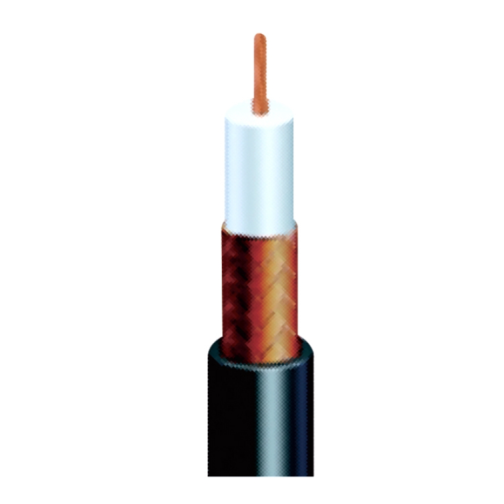
ECX
- Description
- . High frequency coaxial cable of 75ohms chrateristic impedance with annealed copepr wire as inner conductor,
PE insulation, annealed copper wire braid as outer conductor, PVC jacket
- Lists
- .ECX 3C/5C/7C/10C
- Cable Construction
ITEM UNIT 3C 5C 7C 10C Inner
ConductorMaterial - Annealed
copper wireAnnealed
copper wireAnnealed
copper wireAnnealed
copper wireConstruction mm 1/0.5 1/0.8 7/0.4 7/0.5 Diameter mm 0.5±0.02 0.8±0.02 1.2±0.05 1.5±0.05 Insulation Material - PE PE PE PE Thickness mm 1.3±0.1 2.05±0.1 3.05±0.2 3.95±0.2 Diameter mm 3.1±0.2 4.9±0.2 7.3±0.3 9.4±0.3 Color - Natural Natural Natural Natural Outer Conductor Material - Annealed
copper wireAnnealed
copper wireAnnealed
copper wireAnnealed
copper wireIndividual wire diameter mm 0.14 0.14 0.18 0.20 Number of wires
per carrierea 5 (8) 7 (10) 8 (10) 10 (10) Number of carriers ea 24 (16) 24 (16) 24 (16) 24 (16) Lay Length mm 26 (26) 42 (30) 45 (25) 60 (22) Jacket Material - PVC PVC PVC PVC Thickness mm 0.8±0.08 0.9±0.09 1.1±0.11 1.3±0.13 Diameter mm 5.4±0.5 7.4±0.5 10.4±0.5 13.0±0.6 - Technical Details
- Electrical Characteristic
ITEM UNIT 3C 5C 7C 10C Conductor Resistance (max.) Ω/㎞ 91.4 35.9 20.7 13.1 Insulation Resistance (min.) ㏁/㎞ 1000 1000 1000 1000 Dielectric Withstand Voltage AC, V/min 1000/1 1000/1 1000/1 1000/1 Capacitance pF/km 67±3 67±3 67±3 67±3 Relative Propagation Velocity % 66±2 66±2 66±2 66±2 Impedance (MEAN) Ω 75±3 75±3 75±3 75±3 Attenuation
(@ 20℃, 10MHz)dB/km 42 27 22 18
Physical CharacteristicITEM UNIT SPECIFICATION REMARK Insulation
(before heat-aged)Tensile Strength kgf/mm2 ≥ 1.0 According to
KS C 3004 / clause 19Elongation % ≥ 400 Insulation
(after heat-aged)Tensile Strength % ≥ 80 According to
KS C 3004 / clause 20Elongation % ≥ 65 Jacket
(before heat-aged)Tensile Strength kgf/mm2 ≥ 1.0 According to
KS C 3004 / clause 19Elongation % ≥ 200 Jacket
(after heat-aged)Tensile Strength % ≥ 80 According to
KS C 3004 / clause 20Elongation % ≥ 80 Jacket Shrinkage (100℃/4h) % ≥ 10 According to
KS C 3004 / clause 24Cold Bend Test (-20℃/1h) - No visible crack According to
KS C 3004 / clause 23Cold Impact Test (-10℃/2.5min) - No visible crack According to
KS C 3004 / clause 25Conductor Discoloration - No corrosion/discoloration on inner & outer conductor According to
KS C 3002 / clause 3Min. Bending Radius - 6 x Cable Diameter -
- DATA SHEET
- Technical Details
- Electrical Characteristic
ITEM UNIT 3C 5C 7C 10C Conductor Resistance (max.) Ω/㎞ 91.4 35.9 20.7 13.1 Insulation Resistance (min.) ㏁/㎞ 1000 1000 1000 1000 Dielectric Withstand Voltage AC, V/min 1000/1 1000/1 1000/1 1000/1 Capacitance pF/km 67±3 67±3 67±3 67±3 Relative Propagation Velocity % 66±2 66±2 66±2 66±2 Impedance (MEAN) Ω 75±3 75±3 75±3 75±3 Attenuation
(@ 20℃, 10MHz)dB/km 42 27 22 18
Physical CharacteristicITEM UNIT SPECIFICATION REMARK Insulation
(before heat-aged)Tensile Strength kgf/mm2 ≥ 1.0 According to
KS C 3004 / clause 19Elongation % ≥ 400 Insulation
(after heat-aged)Tensile Strength % ≥ 80 According to
KS C 3004 / clause 20Elongation % ≥ 65 Jacket
(before heat-aged)Tensile Strength kgf/mm2 ≥ 1.0 According to
KS C 3004 / clause 19Elongation % ≥ 200 Jacket
(after heat-aged)Tensile Strength % ≥ 80 According to
KS C 3004 / clause 20Elongation % ≥ 80 Jacket Shrinkage (100℃/4h) % ≥ 10 According to
KS C 3004 / clause 24Cold Bend Test (-20℃/1h) - No visible crack According to
KS C 3004 / clause 23Cold Impact Test (-10℃/2.5min) - No visible crack According to
KS C 3004 / clause 25Conductor Discoloration - No corrosion/discoloration on inner & outer conductor According to
KS C 3002 / clause 3Min. Bending Radius - 6 x Cable Diameter -
- DATA SHEET
RG 59 Cable
- Description
- . Electrical and mechanical properties of flexible braided 75 ohm coaxial drop cable
. Transmission of optimal signals and power for voice, data and video applications and indoor cable application for CCTV camera
- Lists
- . RG-59 60%
. RG-59 80%
. RG-59 80% Siamese
- Cable Construction
ITEM DESCRIPTION RG59 60% RG59 80% RG59 Siamese Inner conductor Copper Clad Steel Copper Clad Steel Copper Clad Steel Diameter[mm] 0.81±0.008 0.81±0.008 0.81±0.008 Dielectric Foamed PE Foamed PE Foamed PE Diameter[mm] Nom. 3.45 Nom. 3.45 Nom. 3.45 Outer conductor 
1st shield Bonded Al foil Bonded Al foil Bonded Al foil Thick[mm] 0.04724~0.08128 0.04724~0.08128 0.04724~0.08128 Diameter[mm] 3.60±0.13 3.60±0.13 3.60±0.13 2nd shield Aluminum Braid Aluminum Braid Aluminum Braid Diameter[mm] 0.120±0.01 0.120±0.01 0.120±0.01 Coverage Min. 59% Min. 79% Min. 79% Jacket PVC PVC PVC Diameter[mm] 5.80±0.20 5.80±0.20 5.90±0.20 Thickness[mm] Nom. 0.80 Nom. 0.80 Nom. 0.90 Power Wire
2/18AWGConductor - - Stranded CCA Diameter[mm] - - 15*0.25mm Insulation - - PE Diameter[mm] - - 2.0±0.10 Jacket - - PVC Diameter[mm] - - 4.95±0.2 Thickness[mm] - - Nom. 0.50
- Technical Details
- Electrical Characteristic
ITEM UNIT RG59 DC Resistance Inner Ω/km ≤140 DC Loop Ω/km ≤199.7 Capacitance(pF/m) pF/m 50±3 Relative Propagation Velocity % ≥82
SRL(dB)
5MHz-1000MHz dB ≥20 1000MHz-3000MHz dB 15 Impedance Ω 75±3
AttenuationFrequency (MHz) Max. (dB/100m) 5 2.85 55 6.73 211 12.47 250 13.45 270 13.85 300 14.60 330 15.29 350 15.75 400 16.73 450 17.72 500 18.70 550 19.52 600 20.34 750 22.87 870 24.85 1000 26.64
Mechanical and Envrionmental PerformanceMinimum Braid Wire Tensile Strength ( AL ) 43,000 psi Center Conductor Minimum Break Strength ( CCS ) 91 lbf Corrosion Resistance No signs of corrosion Cold Bend Test No visible damage to jacket Cold Impact Test No visible damage to jacket Maximum Jacket Longitudinal Shrinkage 5% of initial length under test Minimum Center Conductor Bond to Dielectric 5 lbs
RG 11 Cable
- Description
- . Flexible braided 75 ohm coaxial drop cable
. Transmission of RF signals and power for voice, data and video applications and CATV/Internet
- Lists
- . RG-11 60%, 80%, 90%
. RG-11 80%, Tri-shielded with messenger
. RG-11 90%, Tri-shielded with messenger
- Cable Construction
ITEM DESCRIPTION RG11 60% RG11 80% RG11 90% RG11 80%
TRI MRG11 90%
TRI MInner conductor CCS CCS CCS CCS CCS Diameter[mm] 1.63±0.01 1.63±0.01 1.63±0.01 1.63±0.01 1.63±0.01 Dielectric Foamed PE Foamed PE Foamed PE Foamed PE Foamed PE Diameter[mm] Nom. 7.11 Nom. 7.11 Nom. 7.11 Nom. 7.11 Nom. 7.11 Outer conductor 
1st shield Bonded Al foil Bonded Al foil Bonded Al foil Bonded Al foil Bonded Al foil Thick[mm] 0.04724~
0.081280.04724~
0.081280.04724~
0.081280.04724~
0.081280.04724~
0.08128Diameter[mm] 7.25±0.13 7.25±0.13 7.25±0.13 7.25±0.13 7.25±0.13 2nd shield Aluminum Braid Aluminum Braid Aluminum Braid Aluminum Braid Aluminum Braid Diameter[mm] 0.160±0.01 0.160±0.01 0.160±0.01 0.160±0.01 0.160±0.01 Coverage Min. 59% Min. 79% Min. 89% Min. 79% Min. 89% 3rd shield - - - Al foil - Jacket PVC PVC PVC PVC PVC Diameter[mm] 10.16±0.20 10.16±0.20 10.16±0.20 10.16±0.20 10.03±0.20 Thickness[mm] Nom. 1.07 Nom. 1.07 Nom. 1.07 Nom. 1.07 Nom. 1.07 Messenger Conductor - - Galvanized steel Galvanized steel Diameter[mm] - - 1.30±0.05 1.83±0.05
- Characteristics
- Electrical Characteristic
ITEM UNIT RG11 (Single Tape & Braid) RG11 (Tri-shield) DC Resistance Inner ≤40.4 ≤40.4 ≤40.4 DC Loop ≤65.6 ≤54.0 ≤54.0 Capacitance(pF/m) pF/m 50±3 50±3 Relative Propagation Velocity % ≥82 ≥82
SRL(dB)
5MHz-1000MHz 20 20 20 1000MHz-3000MHz 15 15 15 Impedance Ω 75±3 75±3
AttenuationFrequency (MHz) Max. (dB/100m) 5 1.50 55 3.30 211 6.23 250 6.72 270 7.00 300 7.38 330 7.71 350 7.94 400 8.53 450 9.10 500 9.70 550 10.20 600 10.63 750 12.25 870 13.50 1000 14.40
Mechanical and Environmental PerformanceMinimum Braid Wire Tensile Strength ( AL ) 43,000 psi Center Conductor Minimum Break Strength ( CCS ) 363 lbf Corrosion Resistance No signs of corrosion Cold Bend Test No visible damage to jacket Cold Impact Test No visible damage to jacket Maximum Jacket Longitudinal Shrinkage 5% of initial length under test Minimum Center Conductor Bond to Dielectric 5 lbs
RG 6 Cable
- Description
- . Flexible braided 75 ohm coaxial drop cable
. Transmission of RF signals and power for voice, data and video applications and CATV/Internet
- Lists
- . RG-6 60%, 80%, 90%
. RG-6 60% Tri-shielded
. RG-6 60% with messenger
. RG-6 60% Tri-shielded with messenger
- Cable Construction
ITEM DESCRIPTION RG6 60% RG6 80% RG6 90% RG6 60% TRI RG6 60%
MRG6 60%
TRI MInner conductor CCS CCS CCS CCS CCS CCS Diameter[mm] 1.02±0.01 1.02±0.01 1.02±0.01 1.02±0.01 1.02±0.01 1.02±0.01 Dielectric Foamed PE Foamed PE Foamed PE Foamed PE Foamed PE Foamed PE Diameter[mm] Nom. 4.57 Nom. 4.57 Nom. 4.57 Nom. 4.57 Nom. 4.57 Nom. 4.57 Outer conductor 1st shield Bonded Al foil Bonded Al foil Bonded Al foil Bonded Al foil Bonded Al foil Bonded Al foil Thick[mm] 0.04724
~ 0.081280.04724
~ 0.081280.04724
~ 0.081280.04724
~ 0.081280.04724
~ 0.081280.04724
~ 0.08128Dia.[mm] 4.78±0.13 4.78±0.13 4.78±0.13 4.78±0.13 4.78±0.13 4.78±0.13 2nd shield Aluminum
BraidAluminum
BraidAluminum
BraidAluminum
BraidAluminum
BraidAluminum
BraidDia.[mm] 0.120±0.01 0.120±0.01 0.120±0.01 0.120±0.01 0.120±0.01 0.120±0.01 Coverage Min. 59% Min. 79% Min. 89% Min. 59% Min. 59% Min. 59% 3rd shield - - - Al foil - Al foil Jacket PVC PVC PVC PVC PVC PVC Diameter[mm] 6.90±0.20 6.90±0.20 6.90±0.20 6.93±0.20 6.90±0.20 6.90±0.20 Thickness[mm] Nom. 0.80 Nom. 0.80 Nom. 0.80 Nom. 0.80 Nom. 0.80 Nom. 0.80 Messenger Conductor - - - Galvanized steel Galvanized steel Dia.[mm] - - - 1.30±0.05 1.30±0.05
- Characteristics
- Electrical Characteristic
ITEM UNIT RG6 (Single Tape & Braid ) RG6 (Tri-shield ) DC Resistance Inner Ω/km ≤102 DC Loop Ω/km ≤135 for 0.16mm AL Braiding
≤150 for 0.12mm AL Braiding≤121.1 for 0.16mm AL Braiding
≤145 for 0.12mm AL BraidingCapacitance(pF/m) pF/m 50±3 Relative Propagation Velocity % ≥82
SRL(dB)
5MHz-1000MHz dB 20 1000MHz-3000MHz dB 15 Impedance Ω 75±3
AttenuationFrequency (MHz) Max. (dB/100m) 5 2.60 55 5.25 211 10.00 250 10.82 270 11.04 300 11.64 330 12.26 350 12.63 400 13.61 450 14.43 500 15.29 550 16.08 600 16.73 750 18.54 870 20.04 1000 21.49
Mechanical and Environmental PerformanceMininum Braid Wire Tensile Strength ( AL ) 43,000 psi for 0.16mm
31,900 psi for 0.12mmCenter Conductor Minimum Break Strengh ( CCS ) 144 lbf Corrosion Resistance No signs of corrosion Cold Bend Test No visible damage to jacket Cold Impact Test No visible damage to jacket Maximum Jacket Longitudinal Shrinkage 5% of initial length under test Minimum Center Conductor Bond to Dielectric 5 lbs